- Float Switches
- Control Panel
Float Switches
There are several types of float switches and different applications for these switches. Some switches may be used for several applications while others are only for a specific duty. Float switches may be used for pilot duty; to operate control devices such as relays and contactors, thereby never seeing a significant electrical load; or direct duty when they carry a full motor load.
Float switches are manufactured to handle from light to heavy electrical current in a normally open or normally closed application. Some are narrow angle while others are wide angle. The higher amp wide angle float switches are called motor rated, differential, or sometimes piggyback switches when they are manufactured with a special plug on the end.
Narrow angle pilot duty float switches
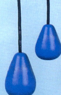
The narrow angle pilot duty switch has been made from an encapsulated mercury switch enclosed in a plastic float (Figure 1). The non-corrosive float may be either solid or hollow and it keeps the switch inside positioned to make contact when the float either floats up (normally open) or hangs down (normally closed). This type of float will typically have an amperage rating if one to two amps. The typical load on this type of switch will be less than half of that which allows the float to last a long time. In the event that a larger control panel with considerable logic built in is serviced by the switch, a heavier switch, frequently around seven amps, is used. In all cases these switches should be protected in the control circuit with a properly rated fuse or breaker.

Figure 1. Floats.
Wide angle pilot duty float switches Whenever using a single float switch for pump control, it must be a wide angle to provide sufficient run time for the pump and to prevent short cycling. If a narrow angle switch is used, the motor will turn off and on with the slightest wave action in the tank. The motor and/or float would soon be destroyed.
Wide angle motor control switches were first designed to provide a reliable and inexpensive on-demand on-off switch for sump pumps. The switches were manufactured as part of the pump and also with a plug designed to receive the pump plug in a piggyback manner. The independent switches have become most popular because they can be replaced without removing the pump. Pumps usually last much longer than these types of switches.
These switches, when used with bigger pumps, require special consideration in both design and installation. In some cases, the use of this type of switch is not suitable. The switch must be designed to carry the full load of the pump. These switches open and close one wire. In the event the pump gets wired wrong, the pump will be hot with the switch trying to break the neutral side. For systems with a Hand-Off-Auto (HOA) switch, the HOA switch must also be rated to carry to full load of the pump. For 230-volt application, there will always be a hot leg in the pump motor.
Two-float pilot duty control
Two-float duty control provides the safest and most accurate control method possible. Two floats are tethered with a four-inch cord length. The drawdown between these two floats will always be the same to the best possible tolerance (usually one-half to one inch). The floats are exposed to very low amperage for the control circuit. The pump is provided electricity only when a definite duty contactor connects all wires to the pump.
The two floats can be set any distance apart without sacrificing the accurate control of the drawdown. For many systems, this is critical. With sensing liquid level with two switches the addition of other components for better operational control, such as counters or elapsed time meters, is less expensive.
General float switch installation
Float switches in general should be installed on a separate support from the pump. This support may be a non-corrosive rack using weighted float switches or a vertical float bar, sometimes called a float tree. In the event of a failure of the pump or control, the device still in operation does not need to be removed, which is of great benefit regarding servicing. The best option is to use a removable vertical float bar so the floats may be removed while maintaining their separation distance. This will allow checking of the drawdown as well as checking operation of the system without disconnecting the floats or changing the drawdown.
Control Panels
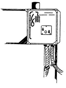
Control panels are protected enclosures that include the control circuits to activate pumps, valves, floats, timers, counters, meters, and alarms. There are a number of different types of control panels, including simplex panels (like seen in Figure 2) that control one pump, duplex panels that control two pumps, and multiplex panels that control more than two pumps. All control panels should be properly electrically protected and should have a handoff automatic (HOA) switch that allows the operator to override the float control system and manually activate the pump. Panels also should have visual and audio alarms and an alarm silence switch. NEMA ratings describe the durability and performance of the control panel enclosure (Table 1). Most treatment system control panels should have a NEMA 4X enclosure.

Figure 2. Electrical control panel.
Alarms
Alarms are used to indicate a failure. If a failure occurs in a pump system, the result will be a rising water level in the tank. When the alarm float is raised, an audible and visual alarm is activated. A switch may silence the audible portion of the alarm. In simplex pump systems, an auto-reset alarm is preferred so when the float deactivates, the audible portion of the alarm is automatically reset. Alarms should be on a separate electrical circuit than the pump motor, but not a dedicated circuit. Place the alarm on a commonly used lighting circuit so if the breaker is thrown, the owner will be notified.
Simplex Panels
Simplex control panels typically provide a motor-rated contactor that will break both legs of the pump motor electrical feed. The float switches would only provide pilot duty (low amperage control current). The panels can have two or three floats, depending on the level of control desired. Two sources of power are desired, one for the pump and one for the pilot alarm circuit. Simplex panels may be timer controlled. Timer controls have “enable” float switches to assure there is enough water to be pumped which then allows the timer to turn the panel on and off.
A wiring diagram should be provided with each panel. The diagram shows two sources of power, the control devices used, and the log circuit to tell how the system will operate. Note that control wiring requires a hot lead and a neutral in the required order to properly operate the system. An installation schematic should also be provided with each panel. It provides an easy reference to see what accessories are provided, and it also shows the required electrical and float connections.
Duplex Panels
Duplex systems operate in the same manner as simplex, but they have an extra pump. The pumps must alternate operation to provide even wear. The alarm float on three float systems should activate the lag pump, as well. The alarm float on a four-float system should be in the third position to notify the owner if a failure occurs. If the alarm were placed in the top position, both pumps would need to fail before the alarm would activate, thus defeating the purpose of the duplex installation.
Both pumps may be fed from the same power supply and the pilot (control circuit), and the alarm must be on the same circuit in order for the alarm condition to activate the reserve pump. Again, the pilot circuit may be on a separate but not dedicated circuit.
Three-Phase Controls
Three-phase controls operate in the same manner as simplex and duplex, but they provide three-phase power to the pumps. Be sure to check pump rotation in three phase. If you switch any two wires on a three-phase motor, the motor will reverse rotation. The pump will run backwards, but only at a small fraction of the design capacity and cavitation can occur, damaging the pump.
Counters and Meters
Counters provide flow indication for timer panels. They count the number of times the pump has been activated. Elapsed time meters tell how long a pump or valve has operated. This is a good way to monitor a pumping system.
Other Control Panel Options
Seal fail notification may be provided for only those pump systems in which the pump has proven manufactured within them. An overload is a device that removes power from the pump in the event it is using excess electricity. A battery backup may be provided if a second electrical circuit is not available for a system. A charger keeps the battery charged so that if power fails and there is a problem, the alarm can still sound. The battery should be capable of sounding the alarm for 12 to 24 hours, depending on the installation.
| Table 1. Types of control enclosures | |
| Enclosure | Explanation |
| NEMA Type 1 General Purpose | To prevent accidental contact with enclosed apparatus. Suitable for application indoors where not exposed to unusual service conditions. |
| NEMA Type 2 Driptight | To prevent accidental contact, and in addition, to exclude falling moisture or dirt. |
| NEMA Type 3 Weatherproof (Weather Resistant) | Protection against specified weather hazards. Suitable for use outdoors. |
| NEMA Type 3R Raintight | Protects against entrance of water from a beat rain. Suitable for general outdoor application not requiring sleetproof. |
| NEMA Type 4 Watertight | Designed to exclude water applied in form of hose stream. To protect against stream of water during cleaning operations, etc. |
| NEMA Type 4X Corrosion Resistant | Designed to exclude water supplied in the form of hose stream and used in areas where serious corrosion problem exists. |
| NEMA Type 5 Dust Tight | Constructed so that dust will not enter enclosed case. Being replaced in part by NEMA 12 Types |
| NEMA Type 6 Submersible | Intended to permit enclosed apparatus to be operated successfully when submerged in water under specified pressure and time. |
| NEMA Type 7 Hazardous Locations Class I – Air Break | Designed to meet application requirements of National Electrical Code for Class I Hazardous Locations (Explosive atmospheres). Circuit interruption occurs in air. |
| NEMA Type 8 Hazardous Locations A, B, C, or D; Class II; Oil Immersed | Identical to Type 7 above, except the apparatus is immersed in oil. |
| NEMA Type 9 Hazardous Locations E, F, or G; Class II | Designed to meet application requirements of National Electrical Code for Class II Hazardous Locations (combustible dusts, etc.) |
| NEMA Type 10 Bureau of Mines | Meets requirements of U.S. Bureau of Mines. Suitable for use in coal mines. |
| NEMA Type 11 Acid & Fume Resistant Oil Immersed | Provides oil immersion of apparatus such that it is suitable for application where equipment is subject to acid or other corrosive fumes. |
| NEMA Type 12 Industrial Use | For use in those industries where it is desired to exclude dust, lint, fibers, & flyings, or oil or coolant seepage. |
Please note that this information was adapted from the Northern Arizona University Department of Civil and Environmental Engineering.


