Just like with your car, it takes energy to speed a car up from a standstill, additional energy to move it up a hill and yet more energy to overcome all the friction of wind, road and parts moving over each other. Water also needs energy to speed it up and lift it to higher elevations and overcome friction as well. In addition water requires energy to pressurize it. A cubic foot of water has more energy if it is under pressure than it has if it isn’t. Water possesses energy of interest in common hydraulic in three forms
Elevation Head
The energy of elevation is the simplest to understand. Carry a bucket of water up a flight of stairs and the work you have done in part goes into potential energy of the water. If water weighs 62.4 lbs/ cu.ft. and you haul it up a 10 ft ladder; you have added 624 ft.- lbs of potential energy to the water. Power relates to how fast you haul it up the ladder. If you hauled it up the ladder in 5 seconds you would be doing 624 ft-lbs/5 seconds or 125 ftlbs/second. A horse power (HP) is defined as 550 ft-lbs per second so you would be working at about HP. Other than friction and inefficiencies a HP pump could do about the same job. For simplicity we describe the energy we just imparted to the water not as 624 ft-lbs but simply 10 feet of “head” meaning the amount of energy that a unit of water would have if lifted 10 feet.
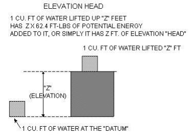
Pressure Head
Water under high pressure has more energy than water under low pressure. Although water is considered incompressible water under pressure is stressed by the pressure and to a small extent the resultant strain is compressing the water and squeezing the bonds and fields in and around the water molecules. Like a bunch of stiff springs the water absorbs the energy into the springs, which then are pushing back against the container and the surrounding water. The energy stored in the water “springs” is distributed over the mass of the water being squeezed. Therefore to get the energy per unit of water you must divide the pressure by the density of water.
Pressure “Head” therefore is defined as Pressure/Density.
Example: Water being squeezed by a pressure of 10 pounds per square inch (psi) is being squeezed at an overall pressure of 144 x 10 pounds per square foot. (There are 144 square inches in a square foot; 12 x 12 = 144). Dividing 1440 pounds per square foot by water’s density of 62.4 lbs/cu.ft (on Earth) results in:
1440 lbs/ft2 / 62.4lbs/ft3 = 23 feet pressure “head”
This is just what we would see if we calculated the pressure under 23 feet of water. So once again we use a convenient equivalent term for the pressure energy, we use feet of head.
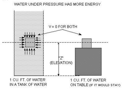
Velocity Head
A baseball resting against the side of your head does not have as much energy to give up as does a fastball that just hit the side of your head. The difference in energy was not due to the elevation of the ball when it hit your head. (In both cases your head was at the same elevation, at least initially.) The difference in energy was not due to the pressure on the ball. Atmospheric pressure was basically the same around both balls. Actually, the speeding ball has a different pressure distribution around it and if it is spinning the differences in pressure from one side to the other could actually cause it to curve. The difference in energy between the two balls is due to the velocity of the ball. Physicists have shown that the energy of velocity turns into energy of elevation as an object rises. Through a ball upward and the height it attains is related to the initial velocity with which it leaves your hand. The velocity (or kinetic) energy of the ball gets turned into elevation (or potential) energy as it rises and slows down. The potential energy turns back into velocity energy as it falls back down. If it were not for air friction a bullet shot straight up would come down with exactly the same velocity (and energy) that it left the barrel with. The same situation exists for water that can be visualized as a bunch of balls being accelerated, flying up and coming back down. Since the velocity energy at the beginning of the bullet’s (or water’s) flight is the same as the potential energy it has at the top of its flight it is convenient, again, to measure that energy by the elevation that the bullet (or water) attains.
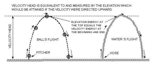
The numerical term which is used for the velocity energy is V2 /2g where g is the gravitational constant 32 ft/sec . Algebraically the units work out nicely; V is velocity which is measured in ft/sec; g is gravity which is measured in ft2 /sec. Multiplying V by itself (V x V = V2 ) results in units of ft2 /sec2 .Dividing one by the other the measuring unit of the term, V2 /2g, comes out to be, once again, feet (of head).
Conservation of Hydraulic Energy
Energy is always conserved. It may turn into heat or noise or be used to break something apart but it never truly goes away. Hydraulic energy is the same. It may change back and forth between the three forms; elevation energy, pressure energy and velocity energy and some of it may be lost to friction (heat) or sound (noise) but it is still all there. In hydraulics we are most concerned about elevation head or energy, pressure head or energy and velocity head or energy. If the additive sum of these does not remain constant as a fluid travels through a system then there must either be energy being added (by a pump for example), or being taken away (by friction or by a generator’s turbine). Therefore if we account for all these terms than we can say that between any two points in a system, point 1 and point 2, energy must be accounted for:
P1/density + V12 /2g + Z1 + Energy Added (pump head) = P2/density + V22 /2g + Z2 + Head Losses
Initial Hydraulic Energy Final Hydraulic Energy
Pressure Head @1 + Velocity Head @1 + Elevation Head @ 1 + Pump Head Added
Equals
Pressure Head @2 + Velocity Head @2 + Elevation Head @ 2 + Friction Losses
This is known as Bernoulli’s Equation and it facilitates the solution of most of the hydraulic problems which need to be solved in on-site systems.
The last two components we need to consider carefully are the pump’s energy (added) and the head losses or friction losses (subtracted)
The head losses are due to friction as it slides along the pipe and bumps into obstacles (turns, bends, expansions and contractions) and the energy which is used up in the water as it slides around itself. Generally these losses are related to the following variables:
a. Pipe’s Length
b. Pipe’s Diameter
c. Pipe’s Material
d. Water’s Velocity
e. Water’s Viscosity
All of these combine to result in the friction loss as water flows through a system. Various theoretical equations and empirical equations have been developed to help us compute these losses.
A useful first situation to study the energy principle is an orifice drilled into the side of a large tank.
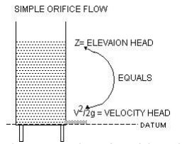
The energy at the surface of the tank consists only of the elevation head because the gage pressure is zero (atmospheric) and the velocity is zero. The energy at the exit of the flow consists only of the velocity head because the gage pressure is also zero (atmospheric) and the elevation head is now zero. Since there is little if any friction loss and no pump between these two points we don’t have to consider those terms either. Therefore, the elevation head at the top, Z, must equal the velocity head at the orifice, V22 /2g.
Z= V22 /2g
Using a little algebra allows us to solve for V.
V2 = (Z* 2g) 1/2
Conservation of Hydraulic Energy Example
Now let’s take a look at the most common situations in treatment systems, pumping effluent from a tank to a disposal field. Consider the diagram below.
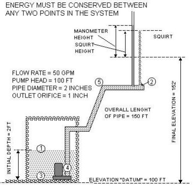
In this case we will assume we know that the pump is producing 100 ft of head. We will also assume that the pipe is frictionless. This is not realistic but let’s learn one thing at a time. It is often of interest to determine the final flow and pressure at the last orifice. The orifice at the end of the pipe constricts the flow down to a 1 inch diameter opening. This problem simplifies that situation considerably by allowing all the water to come out at one point. Let’s determine the theoretical Manometer height. (The squirt height in the field will be less due to air friction and the breakup of the flow into discrete particles or droplets.) Energy must be conserved from point 1 to point 2, point 3 to point 4, point 4 to point 5 and point 5 to point 2. In problems such as this it is always easier to go from a point like point 1 to a point like point 2 because we know some of the energy terms at these points. The pressure is zero at both locations (pt 1 & pt 2) and the velocity is zero at the surface (pt 1) of the tank. In the middle points energy is exchanging between elevation head, pressure head and velocity head and more work would be required to get some of the middle values. Therefore let us consider the conservation of energy between point 1 and point 2.
At point 1: At point 2:
Elevation Head = 102 feet Elevation Head = 152
Pressure Head = 0 psi (gage) Pressure Head = O psi
Velocity Head = 0 ft/sec Velocity Head = ?
Pump Head = 100 ft
Head Loss Due to Friction = 0 ft (assumed)
Therefore simple arithmetic shows us that the Velocity Head at point 2 must be 50 ft.
Velocity Head = V2 /2g = 50
Therefore V2 = 50 * 2g or V = (50 * 2g)0.5
Solving for V results in 56.7 ft/sec.
If the orifice has a diameter of 1 inch, it will have an area of x 12 /4 or 0.785 square inches or 0.785/144 square ft.
If we remember that Q = A x V we can now figure the flow rate.
Q = 56.7 ft/sec x 0.785/144 sq. ft. = 0.31 cfs or 2.31 gallons per second or 138.7 gallons/min
The energy at the manometer will be equal to the energy at the outlet (50 ft). Energy at the manometer will be the sum of the pressure head and the velocity head (in the pipe). The pipe diameter is twice as large as the orifice diameter. Therefore by continuity (remember?) it will have the velocity.
The velocity in the pipe will be 56.7 ft/sec/4 = 14.2 ft/sec.
The velocity energy will be V2 /2g or 14.22 / 2 * 32.2 = 3.13 ft.
Therefore the pressure head at the end of the pipe will be 50 ft – 3.13 ft = 46.87 ft.
It should be obvious that with slow velocities at the end of laterals and small orifices we should see even closer agreement between the velocity head at the orifice and the pressure head measured close by with a manometer.
Friction Loss and Pump Curves
We are almost ready to consider the complete problem of a pump in a tank discharging to a disposal field. We need two more parts:
a. Friction Loss
b. Pump Curves
Friction Loss
There are two kinds of friction loss; friction loss along the length of pipes and friction loss at bends and transitions. The losses at bends and transitions are considered minor but if the pipe velocities are large and there are many bends and transitions the minor losses can build up and be quite considerable. But for now we will only consider the major losses along pipelines. As mentioned above pipeline losses are related to: pipe’s length, pipe’s diameter, pipe’s material, water’s velocity and water’s viscosity. The most common equation used to compute friction losses along a pipe is known as the Hazen Williams formula. This formula can be solved for the head loss in a pipe and results in a working formula which looks like:
Head loss/100 ft of pipe = 100 * (Q/ (0.285 * C * D2.63))1.85
Q = flow in gallons per minute
D = pipe diameter in inches
C = smoothness coefficient
Fortunately, for simple problems we don’t have to solve this by hand. The head loss/100 foot of pipe is often tabulated for our convenience for common pipe sizes and materials. The following page contains such a chart of Schedule 40 PVC a material commonly used in onsite systems. Looking at the chart it becomes apparent that as the flow goes up for a given pipe size the friction loss also goes up. Consider the pump problem solved in the last section. The final flow calculated was to be 138.7 gallons per minute. From the chart we can see that the frictional head loss along the pipe would be about 40 feet. This reduces the final head from 50 down to 40 but only if the pump continues to provide 100 feet of head. With less velocity head at the exit there would be a considerably lower flow rate computed. As it turns out the head a real pump provides will increase as the flow rate decreases but will not increase to the point where the original calculated flow will be sustained. A marriage between the system’s energy requirements and the pumps energy availability will have to be developed to determine the actual final pressure and head. The friction head loss information allows the convenient resolution of more complex pump design problems when used in conjunction with the simplified energy equation and the pump head data prepared by pump manufacturers.
Pump Supplied Energy
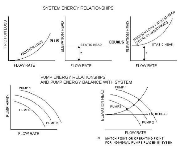
In the previous example pump problem we solved for the pressure and flow at the orifice once we were give information about the pump’s head, which we assumed, was constant. As it turns out any given pump provides a different amount of head for each different flow quantity. And for each different flow quantity the system needs a different amount of energy to overcome the friction. Therefore you can’t solve for the flow until you know the pump head and you don’t know the pump head until you know the flow. (This is like chasing your tail.) Fortunately the energy concept helps again because the amount of energy the pump provides and the amount of energy the piping system needs will come into balance once the system is turned on. The system can’t run at a flow condition which demands more energy than the pump can provide at that flow condition. A balance must be struck. The diagrams below illustrate these points. The first set of graphs show friction loss increasing with flow. The second graph shows the elevation change or static lift which must be supplied by the pump regardless of the flow rate. The third graph shows the summation of the friction loss curve and the static head to create what is called the system curve. The second set of graphs shows first some generic pump curves. Note how the three pumps provide decreasing pressure head as the flow increases. The last graph shows the system curve placed on the same graph with the pump curves. Where the system curve crosses the pump curves are the three potential operating points for the system. Each pump comes to equilibrium with the system at a different combination of flow and head. The designer’s job is to select a pump which provides at least the minimum required pressure at the required flow.
Now, let’s finish this problem off with some real pump data and find out what flow rate and final pressure will result if we put a specific pump in the system. Following the friction loss page is another page of data that contains typical pump curve information. Two make our solution even more accurate it would be worthwhile to add in some of the minor losses that affect the system. These minor losses arise at the pipe fittings, joints, bends, and changes in diameter. There are two ways which are generally used solve for the minor losses:
a. friction loss factors which must be multiplied by the velocity term, V2 /2g
b. equivalent length factors which add a length of straight pipe to the total length of straight pipe which results in the same additional head loss as would the
Looking at the diagram we can see that there are three bends at about 90 degrees. The chart following the pump data shows that for a 2 inch line and 90 degree elbow is equivalent to 9 additional feet of head loss per fitting. With three such fittings there is a net increase of 27 feet of equivalent pipe. This length should be added to the original pipe length when determining the frictional head loss.
Continue the problem until you can determine what actual flow would result from each of the four pumps shown in the pump curve data.
Please note that this information was adapted from the Northern Arizona University Department of Civil and Environmental Engineering.


